VE Foam Maker
Discharge Devices | Model KLF
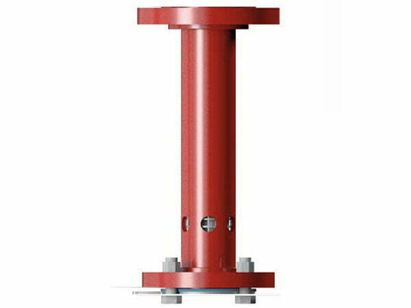
General description
Foam makers are in-line fixed foam aspirating devices. They are used in low expansion foam discharge applications to protect tank farm dikes and other low-level discharge applications.
Foam makers are used in the dike foam delivery system as referred to in design standards such as NFPA 11.
Foam makers are part of a low-level foam delivery system that also incorporates foam storage bladder tanks, proportioning devices and suitable foam concentrates. Foam solution can also be supplied by foam pumping systems or in semi-fixed systems supplied from a portable supply such as a fire brigade appliance.This technical data is intended for trained experts.
For further information, please contact Fomtec or refer to the technical documentation. The contents of this publication are subject to modifications without notice.