Tyr Foam Chamber Discharge Devices | Model KCS

Description

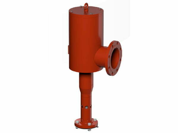
Foam chambers are suitable for the protection of fixed roof-mounted tanks and are to be used as low expansion Type II discharge devices (as defined by NFPA 11) with approved and/or listed foam concentrates and proportioning devices. Foam chambers are designed to apply an expanded foam blanket over the surface of a flammable liquid fire as gently as possible to achieve extinguishment and/or vapor suppression. A deflector positioned on the inside of the storage tank directs the expanded foam back onto the wall of the tank. The foam runs down the wall of the tank onto the liquid surface, minimizing submergence and fuel pick-up thereby maximizing the positive effect of the foam. Low expansion foam deluge systems are the preferred protection for large outdoor tanks of flammable liquids. Typical applications include manufacturing plants, large tank farms, oil refineries and chemical plants. This technical data is intended for trained experts.

For further information, please contact Fomtec or refer to the technical documentation. The contents of this publication are subject to modifications without notice.

Listings and approvals

The foam chamber is UL Listed as part of a fire extinguishing system combining designated foam concentrates, proportioning devices and bladder tanks. Listed system components can be found at www.database.UL.com

  • UL Listed – GFUT.EX16314

NOTE: Other international approval certificates may be available upon request.

Tyr-KCS FoamChamber- UL Listed

Technical data
Construction features

  • Available in 2.5”, 3”, 4”, 6” sizes to cover a wide range of design configurations
  • Painted carbon steel or painted stainless steel for increased corrosion protection
  • Available with ANSI 150 or PN16 flanges
  • Lifting lug/handle to assist with installation and servicing
  • Choice of 2 deflectors: Solid and split (For installation from outside of storage tank)
  • Specifically UL Listed with Fomtec foam concentrates

See more information and tables in the datasheet.

Scope of supply

Ensure that all components are complete and in good condition.

Included:
Foam chamber
Sized orifice (Quantity 1)
Installed vapor seal (Quantity 1)
Inlet flange gaskets (Quantity 2)
Lifting lug to allow safe maneuverability on site

Not Included
Tank mounting flange (sold separately – see table 3.4.1 in datasheet)
Split/solid deflector (sold separately – see table 3.4.1 in datasheet)

Availability

Please contact Fomtec for further information. The product is available directly from Fomtec and official distributors only.

Product variants

  • Also available with galvanized or paint over galvanized finish (Not UL Listed)
  • Various colours
  • Internal paint

Installation

Refer to appropriate installation standards (i.e. NFPA 11,EN13565-2).Do not alter the piping without consulting a system design representative.Foam chambers are compatible with many types of foam concentrate but are only UL listed when used with the specific foam concentrates detailed on www.database.UL.com

Foam chambers are generally installed on the side wall of vertical storage tanks above the maximum product storage level. Piping coupled to the unit can be linked to a fixed foam proportioning system, or terminated a safe distance from the tank, where foam solution can be delivered via mobile fire apparatus or portable foam proportioning equipment.

Care should be taken during the filling of the storage tanks with flammable liquids to ensure that the internal pressure is relieved to avoid rupturing the foam chamber vapor seals due to excessive back pressure. It is recommended to install the deflector before the foam chamber is positioned onto the tank wall studs or mounting flange bolts. If the storage tank is new and access is possible to the inside of the tank then a solid deflector can be used. Use the split deflector when installation has to be made from the outside of the tank. The split deflector can be disassembled into 2 pieces. The section with flange holes can be passed through the flange opening in the tank wall and installed onto the existing studs or mounting flange bolts. After the first part is securely in place, the second half of the deflector can be passed through the flange opening and secured to the first part using the bolts provided.

Always verify that the vapor seal is in place and undamaged due to transportation and installation movement.

Operation

Foam solution can be delivered to the foam chamber in a variety of ways as previously noted.The foam chamber produces foam by introducing air into the foam solution stream. Air is drawn into the foam maker section through a series of annular holes located around the integral foam maker. To prevent obstruction, the air inlet holes are protected by a stainless steel screen (mesh) selected with a perforation size designed to exclude most known nesting birds and insects. The open area of the screen is designed to be not less than the total area of the foam maker air inlet holes. The aluminium foil burst disc is perforated due to the system supply pressure and the expanded foam enters the main mixing chamber where further agitation takes place before been discharged through the oversized outlet and deflecting onto and down the tank wall before rapidly spread across the liquid surface.

Guarantee

For details of warranty, contact Fomtec directly.

Inspections, tests and maintenance

Notice: The owner is responsible for maintaining the fire protection system and devices in proper operating condition. The pilot operated pressure control valve must be kept from freezing conditions and physical damage that could impair its operation.

Warning: Any system maintenance or testing that involves placing a control valve or detection system out of service may eliminate the fire protection capabilities of that system. Prior to proceeding, notify all Authorities Having Jurisdiction. Consideration should be given to employment of a fire patrol in the affected areas.

Vapor seal inspection
Inspection of the vapor seal is recommended to as part of the fire protection system maintenance schedule. As foam chambers are installed at height, care should be taken to ensure a safe working platform or other suitable access is in place before commencing this work. The vapor seal is accessed by removing all but one of the inspection cover bolts. The cover can then be rotated to one side taking care not to damage or dislodge the cover seal. A visual inspection can then be performed to check if the foil vapor seal is still intact.

Vapor seal replacement
If the vapor seal needs replacing the retaining bolts on the vapor seal retaining assembly should be carefully removed and kept secure. The assembly cover can then be removed and the vapor seal replaced. Care should be taken to ensure the correct vapor seal is selected in accordance with the instruction in Table 13.1.2 in the datasheet. The vapor seal assembly cover can then be remounted and the retaining bolts secured to a torque of 90lbs (10 Nm). The inspection cover then be moved back into position taking care that the inspection cover seal is undamaged during the process. The inspection cover bolts can the be inserted and tightened to a torque of 40ft lbs (54 Nm).

Disposal

At end of use the product described here should be disposed of via the national recycling system. Upon request, the manufacturer can take back and properly dispose of the electrical equipment and electronic devices.

Accessories and spare parts

Due to the wide operating range of the foam chambers it is necessary to have different vapor seals depending on the inlet orifice size selected. When ordering spare or replacement vapor seals, care should be taken to check the foam chamber orifice size and match with the correct vapor as shown in table 13.1.1 in the datasheet. The 6” foam chamber has 1 vapor seal option for the full orifice range.

1. When the official purchase order is made for the orifice plate kit, the foam chamber size, the orifice inlet pressure and desired
flow rate must be provided (required).
NOTE: The inlet orifice size will be manufactured to match the pressure and flow information provided in step 2 and assembled with the correct vapor seal. Any modifications made after the release of the foam chamber are the responsibility and at the risk of the authorized purchaser. Changes could include but are not limimted to an entire system redesign, revamping of system components, restocking fees, etc.

2. The final (ordering) part number will contain the required orifice size. Example: An orifice plate for a 2-1/2” foam chamber with a 0.750 inch orifice will be given the part number F21499/0750.

Declaration of conformity

If required, contact the appropriate sales office in Section 5 Availability for further assistance.